Saturday, August 17, 2013
Hello :)
Alright, so I have no pictures for you guys this week! Sorry.
What I worked on this week was finishing up a fair number of circuit boards AND I started work on the RFID project. Specifically, a pro-type was formulated and parts were tracked down. Next up will be to see how well the pro-type fares! :)
Till next week!
Friday, August 9, 2013
The Train Project
Sorry it's been a while since my last post but, Def Con and Black Hat were last week!
This week, I have been inordinately productive which is why this post is likely to be short and is a bit late! Here, I have been working on what I refer to as only the "Train Project" which amounts to increasing the efficiency of trains by 20% or so. The entire idea was inspired by this paper: http://web.ing.puc.cl/~power/paperspdf/dixon/60a.pdf . Thus, I have been spending much of my time pouring over it and going through both the diagrams and the calculations! Also, I got to build two circuits (each of the same circuit design). Lastly, I have been doing a number of calculations. I'd post my work but, it is not very attractive looking. Sorry :( My notes are pretty good looking though...

Some of the guys (random, indeed):

Some of my note pages ;) :


At least, I think they are pretty nice looking. If you disagree, surely you can imagine what my calculations looked like... : /
I will also be doing some inventory and ordering new parts as well as finishing (hopefully) the V4 wikki documentation.
Lastly, I will be engaging in figuring out how to build an RF-ID cloner (unless I forgot something ELSE I will be doing!) in order to help companies improve their security.
Friday, July 19, 2013
V4
Frankly, I had been too busy working to remember to take more than a measly three photos.
Here is one of the boreds baking:

Secondly:

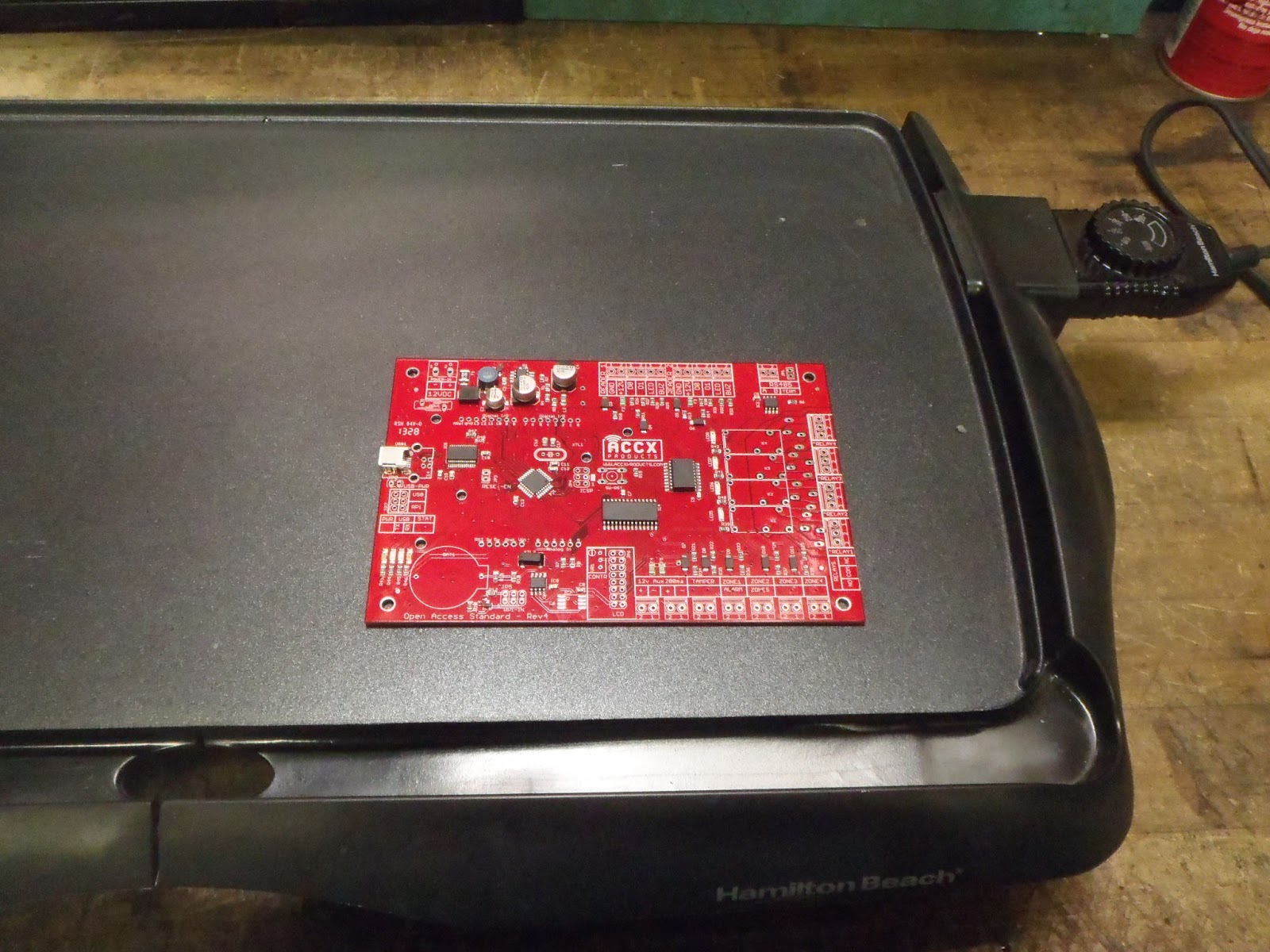
This is one of the "finished" products. I wrote "finished" in quotes as the circuit is complete but, we still needed to attach a few things to the header. I am SO pleased that it worked BEAUTIFULLY the first time! To be fair, I had two very experienced professionals look it over before we checked its functionality and, as a result, I did clean up some of the surface solders. When the second guy grabbed it from me and said that he was "going to take it under the microscope," I didn't know he was being LITERAL! Lol : /
Lastly:

Interesting fact: as the boards bake, they get redder; they go from a bright red to a deep red!
Now, to Wiki the instructions so that others may build their own version (which will not get finished by today-- I'm exhausted)!
Stay tuned for next week when I learn use Solid Works to print something out using the 3D printer! Any ideas as to what I should design?
Here is one of the boreds baking:
Secondly:

This is one of the "finished" products. I wrote "finished" in quotes as the circuit is complete but, we still needed to attach a few things to the header. I am SO pleased that it worked BEAUTIFULLY the first time! To be fair, I had two very experienced professionals look it over before we checked its functionality and, as a result, I did clean up some of the surface solders. When the second guy grabbed it from me and said that he was "going to take it under the microscope," I didn't know he was being LITERAL! Lol : /
Lastly:

Interesting fact: as the boards bake, they get redder; they go from a bright red to a deep red!
Now, to Wiki the instructions so that others may build their own version (which will not get finished by today-- I'm exhausted)!
Stay tuned for next week when I learn use Solid Works to print something out using the 3D printer! Any ideas as to what I should design?
Friday, July 12, 2013
Some of The Equipment and Other Related Things
The soldering paste and applicator:

The soldering iron I have yet to name. Any suggestions?

The only soldering tip which makes one enthusiastic about soldering-- in my experience-- as compared with "lesser" tips ;) :

The soldering iron I so fondly refer to as: the "blow dryer":

A Geiger counter which may be used on a future project (the indeterminate factor being whether THIS particular radiation detector is going to be used). No, we are not going to be dealing with hazardous materials. ;)

Whether you call it a SUPER capacitor or an ULTRA capacitor-- it IS EXTRAordianry!

More Prototyping
First, I built the circuit on a bread board using "macroscopic" parts ("macroscopic" is my personal colloquialism). See below:

What the circuit was designed for:
This is a simple blink circuit. Suppose the LED on the right blinks first, for x
amount of time. The LED on the left will blink for x amount of time once the
right LED ceases to blink. This pattern repeats.
The purpose of it's creation was two-fold. Firstly, there was a surplus of LEDs,
resistor, and capacitors. Secondly, this particular circuit is very forgiving for
the novice; It's pretty tough to blow out the LEDS, you can interchange
resistors and capacitors and get the same circuit behavior (so long as:
tau = R*C = constant), and you can experiment to come to understand
RC-circuit behavior by changing out resistors and/or capacitors, in a
thoughtful and mindful way. Thus, the learner's kit was born and will be
on sale in a matter of time.
To ensure that the prototype circuit was identical to my bread board circuit, I mapped out what I had (i.e. prototype) against what I wanted (i.e. bread board circuit):

The prototype (incomplete at this point in time):

To get a "feel" for the contrast between the "macroscopic" and "infinitesimal" parts I deal with, here is a photo comparing both sizes of transistors:

Needless to say, it is a good thing that the "microscope" pieces are so inexpensive, seeing as how easy it is to loose one of them! : /
This is a picture of the Red Bull I was consuming while working:

( I felt obligated to show my respect to such a precious thing, as one of my sacred source of caffeine!)
It is interesting to note that the transistors were SO small I had to manually cut two of the the stripes of medal backings with an exacto-knife (remember: this is the PROTOTYPE. The official kits are made using machines)! Good thing I am endowed with patience-- not that it wasn't tried!
More on THIS to come (the circuit, not the Red Bull-- well, maybe that too ;) ! ).
Prototyping
Early on, when I began my internship at ACCX Products, inc.(which you can access HERE: http://www.accxproducts.com/content/ ) not only did I learn how to do surface soldering but, I got to build the prototype board. Here is a picture of me working on it:

Shortly thereafter, I "baked" the circuit board. I had never heard of such a thing, previously! But, when you have a high quality fiber glass circuit board, you are doing surface mount soldering (complete with soldering paste), and the parts you are using are something like infinitesimal in size, it is the optimal choice! Here is a picture of the board baking to completion:

As this is my first blog EVER, I hadn't the foresight to take a picture of the soldering paste. Consequently, I will post a picture of the soldering paste sometime next week ( July 18th-July 19th). The board worked beautifully, by-the-way ;)
Prior to all of this I had practiced surface mount soldering with a never-before-used (by ME, that is) hot air soldering iron (which I lovingly refer to as: the "blow dryer"). In preparation of the above prototyping, I should mention.
Also, because I love it so much, I will post pictures of the soldering iron which I love very dearly. Not just because of its NASA-level quality but, also because of the soldering head I use on it. I think I may name him, I love him so much! : /
Subscribe to:
Posts (Atom)